Eline-technology ANPTZ-70-10DN User Manual
Browse online or download User Manual for Camcorders Eline-technology ANPTZ-70-10DN. eLine Technology ANPTZ-70-10DN User Manual
- Page / 42
- Table of contents
- TROUBLESHOOTING
- BOOKMARKS
Rated. / 5. Based on customer reviews
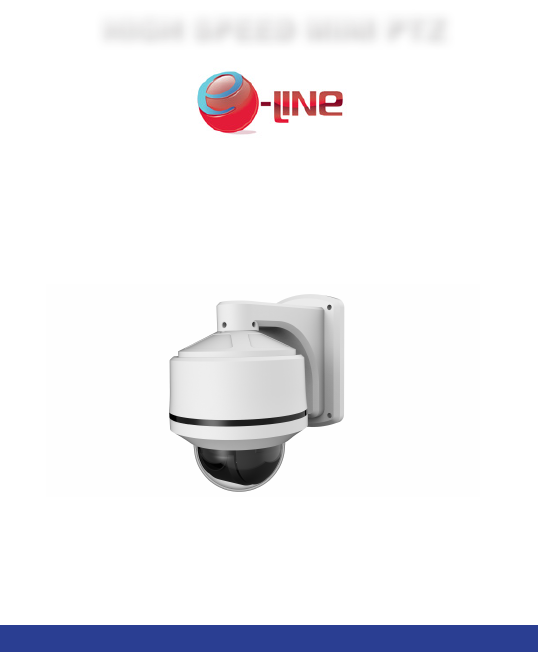
- HIGH SPEED MINI PTZ 1
- Features 2
- Safety Instructions 3
- TABLE OF CONTENTS 4
- 1. GETTING STARTED 6
- 2. CONNECTING THE CAMERA 7
- 2.3 RS485 CONNECTION 8
- 2.4 ALARM INPUT CONNECTION 8
- Changing Protocol Information 10
- 3.2 SETTING THE CAMERA ID 11
- ID Switch is ON or OFF 12
- 1 2 3 4 5 6 7 8 12
- 1 2 Protocol/Baud Rate 13
- 4. INSTALLATION 14
- Installation 16
- 5. USING THE OSD MENU 23
- 5.2 DISPLAY SETUP 24
- 5.3 CAMERA SETUP 25
- White Balance Setup 26
- Auto Exposure Setup 27
- 5.3.2 MOTION SETUP 28
- Parking Action Setup 29
- Alarm Input Setup 29
- 5.3.3 PRESET SETUP 30
- 5.3.4 SWING SETUP 32
- 5.3.5 PATTERN SETUP 33
- 5.3.6 GROUP SETUP 34
- 5.4 SYSTEM INITIALIZE 36
- 6. TECHNICAL SPECIFICATIONS 38
- 7. DIMENSIONS 39
- 8. TROUBLESHOOTING 40
- Manual P.rinted in China v1.1 42
- 01.BSM.18.3000015 42
Summary of Contents
Page 1 - HIGH SPEED MINI PTZ
Installation Guide for setup and conguration.HIGH SPEED MINI PTZ
Page 2 - Features
5Changing Protocol InformationEnglish3. CHANGING PROTOCOL INFORMATIONThe DIP switches on the bottom of the camera control 3 values: 1. The ID of the c
Page 3 - Safety Instructions
5Changing Protocol InformationEnglish3. CHANGING PROTOCOL INFORMATIONThe DIP switches on the bottom of the camera control 3 values: 1. The ID of the c
Page 4 - TABLE OF CONTENTS
ID Switch is ON or OFF1 2 3 4 5 6 7 8Value 1 2 4 8 16 32 64 1281 ON OFF OFF OFF OFF OFF OFF OFF2 OFF ON OFF OFF OFF OFF OFF OFF3 ON ON OFF OFF OFF OFF
Page 5
ID Switch is ON or OFF1 2 3 4 5 6 7 8Value 1 2 4 8 16 32 64 1281 ON OFF OFF OFF OFF OFF OFF OFF2 OFF ON OFF OFF OFF OFF OFF OFF3 ON ON OFF OFF OFF OFF
Page 6 - 1. GETTING STARTED
9InstallationEnglish4. INSTALLATION4.1 INSTALLATION WARNINGSMake sure to install the camera in a location that can support the camera weight.Make sure
Page 7 - 2. CONNECTING THE CAMERA
9InstallationEnglish4. INSTALLATION4.1 INSTALLATION WARNINGSMake sure to install the camera in a location that can support the camera weight.Make sure
Page 8 - 2.4 ALARM INPUT CONNECTION
11InstallationEnglish4.3 CEILING MOUNTING (INDOOR ONLY)Camera is not weatherproof if installed using this method. Use the included wall mount or acces
Page 9
11InstallationEnglish4.3 CEILING MOUNTING (INDOOR ONLY)Camera is not weatherproof if installed using this method. Use the included wall mount or acces
Page 10 - Changing Protocol Information
13InstallationEnglish5. Drill holes for the mounting screws (x4) and the cables and run the cables through the hole. Ceiling/Flush mounting screws66.
Page 11 - 3.2 SETTING THE CAMERA ID
13InstallationEnglish5. Drill holes for the mounting screws (x4) and the cables and run the cables through the hole. Ceiling/Flush mounting screws66.
Page 12 - 1 2 3 4 5 6 7 8
iEnglishFeatures• 1/3” Sony EX-View™ II 960H, 700+ TVL• 10x Optical/10x Digital Zoom• Polaris Vision low light viewing• True Day/Night with IR Cut Fil
Page 13 - 1 2 Protocol/Baud Rate
15InstallationEnglish4.4 FLUSH MOUNTING (INDOOR ONLY)Camera is not weatherproof if installed using this method. Use the included wall mount or accesso
Page 14 - 4. INSTALLATION
15InstallationEnglish4.4 FLUSH MOUNTING (INDOOR ONLY)Camera is not weatherproof if installed using this method. Use the included wall mount or accesso
Page 15
17InstallationEnglish5. Insert the bottom of the camera through the hole and attach it to the ceiling using the ceiling/flush mounting screws (3x).5Ca
Page 16 - Installation
17InstallationEnglish5. Insert the bottom of the camera through the hole and attach it to the ceiling using the ceiling/flush mounting screws (3x).5Ca
Page 17
19Using the OSD MenuEnglishSubmenus:• System Information: View information about the camera.• Display Setup: Configure camera OSD.• Dome Camera Setup:
Page 18
19Using the OSD MenuEnglishSubmenus:• System Information: View information about the camera.• Display Setup: Configure camera OSD.• Dome Camera Setup:
Page 19
21Using the OSD MenuEnglish• F OCUS MODE [AUTO/MANUAL/SEMIAUTO]: Sets camera focus mode. If set to SEMIAUTO, manual focus is used in preset operation,
Page 20
21Using the OSD MenuEnglish• F OCUS MODE [AUTO/MANUAL/SEMIAUTO]: Sets camera focus mode. If set to SEMIAUTO, manual focus is used in preset operation,
Page 21
23Using the OSD MenuEnglish5.3.2 MOTION SETUPMotion Setup allows you to setup the motion settings of the camera.• MOTION LOCK [ON/OFF]: When set to O
Page 22
23Using the OSD MenuEnglish5.3.2 MOTION SETUPMotion Setup allows you to setup the motion settings of the camera.• MOTION LOCK [ON/OFF]: When set to O
Page 23 - 5. USING THE OSD MENU
iEnglishFeatures• 1/3” Sony EX-View™ II 960H, 700+ TVL• 10x Optical/10x Digital Zoom• Polaris Vision low light viewing• True Day/Night with IR Cut Fil
Page 24 - 5.2 DISPLAY SETUP
25Using the OSD MenuEnglish• ALARM TYPE [Normal OPEN(N.O) / Normal CLOSE](N.C)]: Sets sensor input type.• ALARM ACTION [NOT USED/HOME/PRESET/GROUP/PAT
Page 25 - 5.3 CAMERA SETUP
25Using the OSD MenuEnglish• ALARM TYPE [Normal OPEN(N.O) / Normal CLOSE](N.C)]: Sets sensor input type.• ALARM ACTION [NOT USED/HOME/PRESET/GROUP/PAT
Page 26 - White Balance Setup
27Using the OSD MenuEnglish5.3.4 SWING SETUPYou can setup up to 8 swings.During a swing, the camera moves between 2 Preset positions repeatedly. When
Page 27 - Auto Exposure Setup
27Using the OSD MenuEnglish5.3.4 SWING SETUPYou can setup up to 8 swings.During a swing, the camera moves between 2 Preset positions repeatedly. When
Page 28 - 5.3.2 MOTION SETUP
29Using the OSD MenuEnglishTo create a Pattern using keyboard controller shortcuts:• Press [1~4] and press [Pattern] for 2 seconds. Define the pattern
Page 29 - Alarm Input Setup
29Using the OSD MenuEnglishTo create a Pattern using keyboard controller shortcuts:• Press [1~4] and press [Pattern] for 2 seconds. Define the pattern
Page 30 - 5.3.3 PRESET SETUP
31Using the OSD MenuEnglish• ###: Action number.• DWELL: Dwell time in mm:ss between 1 sec.~4 min.• OPT: Preset speed (2~360) when preset is selected.
Page 31
31Using the OSD MenuEnglish• ###: Action number.• DWELL: Dwell time in mm:ss between 1 sec.~4 min.• OPT: Preset speed (2~360) when preset is selected.
Page 32 - 5.3.4 SWING SETUP
33Technical SpecificationsEnglish6. TECHNICAL SPECIFICATIONSII DCC DAH weiV-xE ynoS "3/1rosneS egamIC / PAL (Model dependant)STNtamroF oediV)V( 4
Page 33 - 5.3.5 PATTERN SETUP
33Technical SpecificationsEnglish6. TECHNICAL SPECIFICATIONSII DCC DAH weiV-xE ynoS "3/1rosneS egamIC / PAL (Model dependant)STNtamroF oediV)V( 4
Page 34 - 5.3.6 GROUP SETUP
iii TABLE OF CONTENTSEnglish1. Getting Started . . . . . . . . . . . . . . . . . . . . . . . . . . . . . . . . . . . . 11.1 Optional Accessories . .
Page 35
35TroubleshootingEnglish8. TROUBLESHOOTINGThere is no picture at night• Camera is capable of seeing in extremely low light conditions (0.02 Lux), but
Page 36 - 5.4 SYSTEM INITIALIZE
35TroubleshootingEnglish8. TROUBLESHOOTINGThere is no picture at night• Camera is capable of seeing in extremely low light conditions (0.02 Lux), but
Page 37
Product Made in China under ISO9001 & ISO1400 standardsManual P.rinted in China v1.101.BSM.18.3000015eLineTechnology.com
Page 38 - 6. TECHNICAL SPECIFICATIONS
iii TABLE OF CONTENTSEnglish1. Getting Started . . . . . . . . . . . . . . . . . . . . . . . . . . . . . . . . . . . . 11.1 Optional Accessories . .
Page 39 - 7. DIMENSIONS
1Getting StartedEnglish1. GETTING STARTEDCeiling/Flush Mount ScrewsInstruction ManualCamera and Wall MountFoam PadWall Mount ScrewsBefore you start, e
Page 40 - 8. TROUBLESHOOTING
1Getting StartedEnglish1. GETTING STARTEDCeiling/Flush Mount ScrewsInstruction ManualCamera and Wall MountFoam PadWall Mount ScrewsBefore you start, e
Page 41
3Connecting the CameraEnglish2.3 RS485 CONNECTIONFor PTZ control, connect this line to keyboard controller or DVR. To control multiple cameras at the
Page 42 - 01.BSM.18.3000015
3Connecting the CameraEnglish2.3 RS485 CONNECTIONFor PTZ control, connect this line to keyboard controller or DVR. To control multiple cameras at the
Related products and manuals for Camcorders Eline-technology ANPTZ-70-10DN
 (26 pages)
© 2020, manymanuals.com. All rights reserved. | 2.734 s |
 Manymanuals.com
 Manymanuals.de
 Manymanuals.fr
 Manymanuals.it
 Manymanuals.pl
 Manymanuals.cz
 Manymanuals.es
 Manymanuals-pt.com
Comments to this Manuals